<<You Can Use Assemby To Complete This Assignmment!>>
Purpose: The purpose of this lab is to learn how to interface a standalone PIC chip to PICKit3 device. This lab contains three parts:
- Interfacing the Chip to the PICKit3 device
- interfacing the PIC chip to a 7-Segment Device
- Design a Simple Counter
- Learn about Fritzing
- Learn how to do schematic capture using Eagle
Parts Required:
- Jumper cables (35-40)
- 1 10K ohm resistor (1)
- 220-330 ohm resistors (10)
- Seven-segment device (1)
- PICKit3 and USB connector (1)
- Breadboard (minimum of 40 rows are required) (1)
- PIC18F45K20 chip (through) (1)
- Push-button switch (1)
- LED (1)
Useful Links:
- Here is the DEMO board Spec.
- To learn about various functionalities of this PIC chip please refer to the data sheet for PIC18F45K20 microcontroller.
- Using this poster you can see how PICKIT3 Debugger can be connected to the board and your PC.
- There are several useful datasheets regarding the DEMO Board that you can review.
Procedure:
Part I - Interfacing the Chip to the PICKit3 device
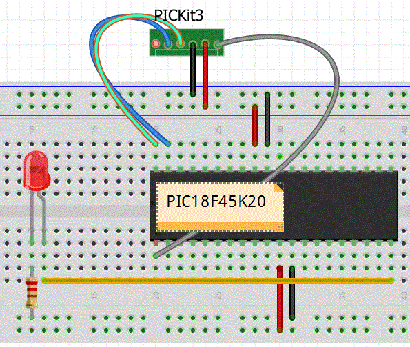
Purpose: Using the provided 40-pin PIC18F45K20 Chip build the cuircuit shown below.
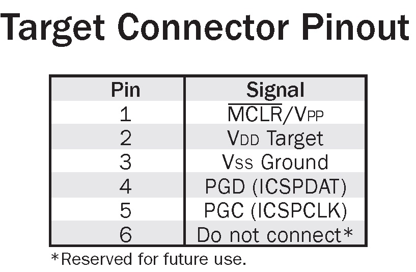
- The connection for interfacing the PICKit3 and the chip is shown in the poster.
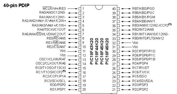
- Note that the PINOUT schematic for PIC18F45K20 is provided for you to make sure how the connections are made.
- In our circuit below we are assuming RD1 (Pin 20) is connected to the LED.
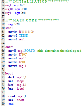
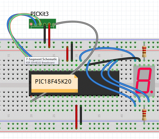
- Connect PICKit3 to the board, as shown below. Load your LED Blinking program into the chip. Make sure the LED blinks. Your program will look something like the program listing below.
NOTE: In case you are having trouble communicating with the chip review the following steps:
- In case you get the following error message: "Target Device ID (0x0) does not match..." most likely your wires are not making contact properly or they are not properly connected. Make sure all your connections are properly made between the devices.
- Make sure Vdd is connected to the Power and Vss is connected to the Ground.
- Make sure in your simulator the PICKit3 is selected and POWER selection is configured properly.
- Make sure your device is set to PIC18F45K20
Part II - Interfacing the PIC chip to a 7-Segment Device: In this part you learn how to interface the PIC chip to a 7-segment device.
- Read the program example on page 270 of your textbook. You must make sure you understand the program. Make sure you can compile the program.
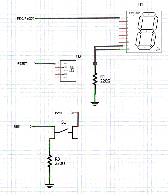
- Construct the circuit below and interface the PIC to the 7-Segment chip. In order to complete the schematic you need to refer to the spec. sheet to learn more about the PINOUT for 7-Segment device. Note that in this figure we assume the 7-Segment device is Common-Cathod.
- Modify your program to ensure it works with Common-Cathod.
- You should also modify the program listing such that the program counts from 0 to 9 in a repeating fashion. All numbers must clearly show up (no extra delay in between or skipping is acceptable).
- Load the program into the chip. In the figure below we have provided a video as to how your program should operate.
 |
VIDEO HERE |
| |
|
Part III - Design a Simple Counter: In this part you are required to design a counter using a single 7-Segment device that stops counting when a push-button switch (connected to RB5) is activated. When the switch is released (disabled) the counting must continue until it reaches F. If the display is larger than 9, the dot LED on the 7-segment must be turned on. After reaching F, the counting must re-start from zero.
- After you ensured that your program and circuit are fully functional you are required to draw the full schematic. To do this go to http://fritzing.org/home/ and download the latest version of Fritzing. (See class syllabus for more tools. You can use other tools!)
- Practice with the program and learn how to use it. You can download and use this Fritzing example circuit as a starting point. - You can use this library part for in Fritzing to create your PIC.
- Generate a complete schematic for your circuit. You should have something like the circuit below. Note that in your schematic all pin numbers and functional names must be clearly identified (e.g., RD1/Pin 23). Use the provided pin out for more information.
- NOTE: A very good Schematic Capture tool is Eagle (download Eagle from AutoDesk - Eagle software was made by CadSoft). If you signup with AutoDesk as a student you can get access to all their tools for 3 years! After you downloaded Eagle, download Sparkfun's libraries. At this point you are ready to practice. A very good tutorial for Eagle is available. Follow this tutorial until the end! You will learn plenty! It is up to you which tool you want to use. However, learning Eagle will be very helpful for your Senior Design Project.
- Here is a very cool schematic capture called EasyEDA- Here is a good tutorial
What to Submit:
- Problem statement for Part III only.
- A complete flow chart of your program (must be done with computer) - Part III only.
- Take a snapshot of your code - you must have appropriate comments - codes without comments will not receive grade. Your code must include proper format as described in class.
- Submit a complete schematic of your circuit (this will be similar to the figure below).
- Submit a complete layout of your circuit (this is similar to the figure above)
- Explain clearly what will happen if you remove the pull-down resistor and why.
- Demonstrate that your 7-Segment project is working.
- Finally, design a hypothetical game: You must have at least one output and one input. You do NOT have to build the game. However, you must complete the flowchart for your game and clearly describe the objective of the game. We need to talk about your design for 5 min. in class.
