Interfacing PIC18F45K20 Microcontroller to 7-Segment
<<Use Assembly To Complete This Assignment!>>
Purpose: The purpose of this lab is to learn how to interface your PIC to a 7-segment device
- Interfacing the Chip to the PICKit3 device
- interfacing the PIC chip to a 7-Segment Device
- Design a Simple Counter
Parts Required:
- Jumper cables (35-40)
- 1 10K ohm resistor (1)
- 220-330 ohm resistors (10)
- Seven-segment device (1)
- PICKit3 and USB connector (1)
- Breadboard (minimum of 40 rows are required) (1)
- PIC18F45K20 chip (through) (1)
- Push-button switch (1)
- LED (1)
Useful Links:
- To learn about various functionalities of this PIC chip please refer to the data sheet for PIC18F45K20 Microcontroller.
Procedure:
Part I - Interfacing the PIC chip to a 7-Segment Device: In this part you learn how to interface the PIC chip to a 7-segment device.
- Read the program listing in the slides. You must make sure you understand the program. Make sure you can compile the program as is. Note that you can use PORT D is you like.
- Make sure you have all your configuration bits included, similar to previous projects!
- Make sure you review Table Pointers first (Read more.)! Pay attention to the details of the code as you type it.
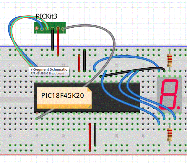
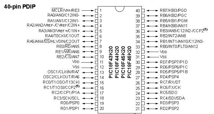
- Construct the circuit below and interface the PIC to the 7-Segment chip. In order to complete the schematic you need to refer to the spec. sheet to learn more about the PINOUT for 7-Segment device. Note that in this figure we assume the 7-Segment device is Common-Cathode.
- You may want to modify your circuit to ensure it works with Common-Cathode.
- Make sure you can display number 8. Use an external power source all 7 LEDs are not turned on.
- Change the displayed value and make sure you understand how the program works.
- The schematic below is NOT showing the entire circuit.
 |
 |
| |
|
NOTE: In case you are having trouble communicating with the chip review the following steps:
- In case you get the following error message: "Target Device ID (0x0) does not match..." most likely your wires are not making contact properly or they are not properly connected. Make sure all your connections are properly made between the devices.
- Make sure Vdd is connected to the Power and Vss is connected to the Ground.
- Make sure in your simulator the PICKit3 is selected and POWER selection is configured properly.
- Make sure your device is set to PIC18F45K20
Part II - Design a Simple Counter: In this part you are required to design a counter using a single 7-Segment device. The counter should count from 1-9.
- Make sure you can do Part I first.
- Change the program listing above such that you loop through the CODEADDR. This can be accomplished by changing TBLWT* to TBLWT*+ . Read more.
- Note that you need to add a delay between each count so the user can see the number. Use a delay subroutine similar to before.
- After you ensured that your program and circuit are fully functional you are required to draw the full schematic. You can do this with many different tools:
- EasyEDA: Another very good and easy schematic capture is called EasyEDA- Here is a good tutorial. If you use EasyEDA use can use this Library. Alternatively you can use this.
- FRITZING: Go to http://fritzing.org/home/ and download the latest version of Fritzing. (See class syllabus for more tools. You can use other tools!) Practice with the program and learn how to use it. You can download and use this Fritzing example circuit as a starting point. - You can use this library part for in Fritzing to create your PIC.
- EAGLE: A very good Schematic Capture tool is Eagle (download Eagle from AutoDesk - Eagle software was made by CadSoft). If you signup with AutoDesk as a student you can get access to all their tools for 3 years! After you downloaded Eagle, download Sparkfun's libraries. At this point you are ready to practice. Another very good tutorial for Eagle is available. Follow this tutorial until the end! You will learn plenty! It is up to you which tool you want to use. However, learning Eagle will be very helpful for your Senior Design Project.
- Generate the complete schematic for your circuit. Note that in your schematic all pin numbers and functional names must be clearly identified (e.g., RD1/Pin 23).
What to Submit:
- Make sure your program displays 1 through 9. Demonstrate your program.
- Submit the complete schematic. Make sure you have your name on the schematic.


