<<You Can Use **C** To Complete This Assignmment!>>
Make sure you answer to all the quesitons!
Revised: April 4, 2017
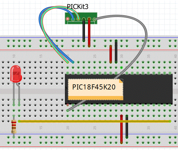
Purpose: The purpose of this lab is to learn how to program PIC18F45K20 using C language and XC8 compiler. Refer to Lab 7 for more information. This lab contains the following parts:
- Writing a simple C-Code to blink an LED
- Using C Library Functions
- Understanding digital input using XC8
- Combining C code and Assembly
- Difference between data types
Parts Required:
- Scope - to measure the output signal
- Switches (2)
- Jumper cables (35-40)
- 1 10K ohm resistor (1)
- 220-330 ohm resistors (10)
- Seven-segment device (1)
- PICKit3 and USB connector (1)
- Breadboard (minimum of 40 rows are required) (1)
- PIC18F45K20 chip (through-hole) (1)
- Push-button switch (2)
- LEDs (7)
- PICKit3 Demo Board (optional inly if you have to)
Useful Links:
Procedure:
Part I - Writing a simple C-Code
Purpose: Write a simple C-Code for your PIC18F45K20 chip to flash an LED.
Download MPLAB XC8. Make sure you select the correct version for your operating system.
After you properly installed the compiler, open an existing project in MPLAB X.
Open an existing project in MPLAB X. Go to File --> Project Properties. Under Compiler Tool Chain you should see xc8 option as shown below:

- Review MPLAB XC8 Getting Started Guide document and learn how to create a C Project.
- Create a C source code file (with extension .c) and use the following code to blink an LED connected to PORT RD1. Your code will look something like this (type the source code below):

NOTE: In case you are having trouble communicating with the chip review the following steps:
- In case you get the following error message: "Target Device ID (0x0) does not match..." most likely your wires are not making contact properly or they are not properly connected. Make sure all your connections are properly made between the devices.
- Make sure Vdd is connected to the Power and Vss is connected to the Ground.
- Make sure in your simulator the PICKit3 is selected and POWER selection is configured properly.
- Make sure your device is set to PIC18F45K20
Part II - Using C Library Functions: You become familiar with using different libraries in xc8.
- Download the following Math_Function C code and compile it.
- Part II Questions: Answer the following questions:
- Find the math.h library. What is the path to this file?
- What are the starting and ending addresses for buffer_1?
- Using a Watch window similar the one shown below, check the values saved in buffer_3. Take a snapshot of the contents of buffer_3.
- Refer to MPLAB XC8 User Guide. Search for the square root function. Write a simple code to take the square root of 25. Show a snapshot of your code (exclude the header).
- What happens if you take the square root of 26? Explain. What do you see? Take a snapshot of your Watch window.
- What is the difference between defining buffer_3 as an integer, char, double, or float array? Create a table and show your answers in the table. Give an example for starting and ending address for each case.
- Assuming b is defined as float, what will be the value of b = round(sqrt(25))?
- Read the class slides. Modify the program to generate a random number on PORTD.
Include your code in your report. Show a snapshot of your code.
- Examine the C Code below. Explain what the value of c as it appears. You may want to simulate the code.
- What does memset (x,y,z) do?
| 
|
 |
Part III - Understanding Digital Inputs Using XC8: In this part you become familiar with how to setup IO ports as digital Inputs. YOU NEED A SCOPE for this section!
- READ & REVIEW the program example here. Carefully, examine the code. Pay attention how the debouncing is implemented. This code allows you to connect the input to PORTE0.As long as the input is high the eight LEDs on PORTD will be flashing (shifting) - Note that it is possible to connect PORTD to a 7-segment and cycle through its LEDs. When the input is asserted to be low, the LEDs stop shifting (do not use your demoboard).
- PROGRAM: Change the code such that when one input (SW1) is pressed the shifting is from right to left. When the other switch (SW2) is pressed the LEDs start shifting the opposite direction. Note: It may be necessary to pull up the input pin. Build the circuit on the prototype board and make sure your code works. You must be able to show this to your instructor.
- Part III Questions: Answer the following questions (use the data sheet for PIC18F45K20) :
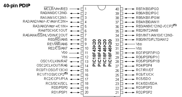
- Which registers are associated with setting up PORTE - name them. (HINT: there are 5 registers)?
- Which registers are associated with setting up PORTB - name them. (HINT: there are 10 registers)?
- Refer to Table 1. Which IO ports have their own internal (weak) Pull-Ups?
- What is the purpose of WPUB register?
- REx is typically multiplexed with ANy. What is ANy refers to?
- How many different ways asm code can be combines in the C code? Show them. (HINT: There are TWO different way)
- Consider the following assembly and C codes:
- Q EQU 0x11 & MOVLW 0x12 & MOVWF Q
- char Q; Q=0x12;
Answer the following questions:
- Are these performing the same operation?
- Which one do you think will be executed faster? Why?
- Is there any difference between these two codes in terms of memory assignment? (HINT: You may want to run both codes and use teh Stopwatch.
- Using an Scope specify what is the the exact delay when you have Delay1TCYx(100) or __delay(); Take your own snapshot from the scope. Do not copy! Make sure you can read the grids on the scope.
- Using an Scope specify what is the the exact delay when you have Delay1TCYx(1000) or __delay(); Take your own snapshot from the scope. Do not copy! Make sure you can read the grids on the scope. You can do this on the second port.
WHAT TO SUBMIT: Use the template!
- Answer to Part I Questions (15 points).
- Answer to Part II Questions. (15 points).
- Answer to Part III Questions. (15 points).
- Make sure Part III (shifting LED) is fully working. (25 points).
- Provide the following for Part III: (30 points).
- Draw the flowchart for your program. Your decision blocks must be clearly identified.
- You must draw your complete circuit schedmatic; make sure you include all the components. You can use Digikey Schematic capturer.
- Take a snapshot of the heading of your code. In the heading you should clearly explain the purpose of your program. Describe all the inputs and outputs in your program.
- Using the simulator you must clearly prove that your design works for all the cases. Show a snapshot of your simulator.
- Make sure you have the snapshot from the scope.
*** ATTENTION: You must work on this assignment individually! If ANY PART of this assignment, including snapshots, is shared between two or more students all parties will receive ZERO. Absolutely no exceptions! ****
______________________ FOR PRACTICE ONLY ___________________________________
Prat IV - Parking Counter (design Problem): In this part you need to design an up/down counter to count the number of cars going into and leaving the D-parking at SSU. The idea is that you have two digital input switches, say A & B. If switch A is enabled first and then switch B is enabled, the value on the 7-segment display should increases, starting with zero. Otherwise, If switch B is enabled first and then switch A is enabled, the value on the 7-segment display should decreases. Also, you must make sure if only one switch is pressed and the second one is not pressed after some times, the count should be ignored and start over (that is if A followed by nothing after 2 seconds, then the count should not change). Assume we never have a case that a single switch is pressed multiple times before the other switch is enabled. For simplicity, the maximum and minimum count values are assumed to be 9 and zero, respectively. You must use C code. You can use the code example here to display values on your 7-Segment. Pay attendtion to how we do the code!
Take a snapshot of your code - you must have appropriate comments - codes without comments will not receive grade. Your code must include proper format as described in class. (solution)
Draw the finite state machine diagram for this system identifying the transition between various states of the switches.
Part V - Combining C code and Assembly: In this part we discuss how to pass variables between C and assembly:
- Read the program example for ccombining C and assembly. Carefully, examine the code. Pay attention to how the variables are passed from one function to another.
- How many different ways asm code can be combines in the C code?
- Explain how a variable which is defined as Global can be passed to #asm portion of the code.
- How is #asm portion of the code is ended?
- What is the difference between the following asm commands?
You may want to run the code and enable the Variables window to see what happens (as shown below).


