Using ADC features in PIC18F45K20 Microcontrollers & Interfacing to LCD
Purpose: The purpose of this lab is to learn how the ADC operates. This lab contains the following parts:
- Programing ADC Unit in the PIC
Parts Required:
- Jumper cables (35-40)
- Potentiometer (1)
- PICKit3 and USB connector (1)
- Breadboard (minimum of 40 rows are required) (1)
- PIC18F45K20 chip (through-hole) (1)
- Push-button switch (2)
- LEDs
- LCD (1)
- PICKit3 Demo Board (optional)
Useful Links:
- Download MPLAB XC8
- To learn about various functionalities of this PIC chip please refer to the data sheet for PIC18F45K20 microcontroller.
- Another Circuit Drawing Tool (Digikey)
Procedure:
Part 1 - LCD Display
Purpose: In this section you learn how to interface the PIC with an LCD device - nothing to submit for this section; just do it!
- Read about how to interface the PIC to your LCD. Correction: In the schematic make sure you connect the Vo to ground (you can do this directly or use a resistor); connect VDD to 5V and connect VSS to ground.
- Setup the PIC-LCD circuit as shown here. (See the correction note above!)
- Implement the PIC-LCD C code. Review the configuration setup.
- Make sure the LCD operates properly.
- Nothing to submit in this section.
Part 2.A - Programing ADC Unit in the PIC
Purpose: In this section you learn how to code the ADC module in the PIC
- Read Section 19 in PIC18F45K20 very carefully.
- Review how an analog actuator (e.g., an accelerometer) can be connected to ADC in PIC . Note that in this case the analog input is connected to RA0. You can replace the analog device with a simple potentiometer.
- Using ADC example C code build implement the circuit and make sure everything works. You must do this part first. Make sure RA0 is set to an analog input.
- Nothing to submit in this section.
Part 2.B - Programing ADC Unit in the PIC and displaying the input on an LCD
Purpose: In this section you should write a code to activate the ADC module in the PIC and then display the analog input value on LCD.
- Write a program such that by changing the potentiometer on the board, the output of the 10-bit ADC (ADRESH/L) changes. You must display the exact voltage value (in decimal) on an LCD display. Your displayed values should be very close to what you read form the multimeter. You need to display values using at least one decimal point (e.g. 2.1V). You can use RA0 as you input (optional). Clearly show all the register settings in PIC. Note: Remember: The key challange is how to display numbers.
- You can set the acquisition time to 48 usec (Taqu-time) and set conversion time to 4 usec (TAD = 4usec).
- Make your your code works. Nothing to submit.
Part 2.C - Programing ADC Unit in the PIC display the input on an LCD, and formal the display
Purpose: In this section you learn how to manipulate the displayed values on the LCD.
- Repeat the program in Part 2.B.
- Modify your code such that if the input analog signal is equal or above a certain value (say 2.0 V) the display shows HIGH in the second row (line), otherwise the LCD displays LOW. The actual input value must be displayed on the first line of the LCD.
- What to submit:
- Make sure you use the template. Write the problem statement. Make sure you have a conclusion.
- Complete schematic of the circuit; all power lines and programming lines, as well as used IO GPIO ports must be shown clearly on paper. You must use a Circuit Drawing Tool (Digikey is an option).
- Submit the flowchart for the program.
- Show all the configuration bits in the program - take a snapshot of your configuration portion of your code.
- Make sure all your information on the header of your code is correct and up-to-date. Take an snapshot.
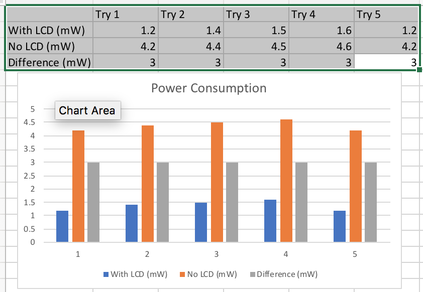
- Measure power consumption of your circuit with and without LCD. Try at least 5 times. Make sure your measurements are correct. You need to plot the results using Excel (as shown below). Explain how you measured the power.
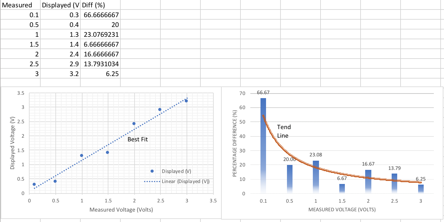
- Using Excel, show how closely your displayed values are compared with actual input analog signal. Create a graph using Excel and compare the values from 0-3V. Your x-axis should represent the measured and y-axis should represent your displayed values (see the chart below). Make sure you add a trend line. Is the trend line linear?
- Using Excel, based on your results above, show the difference between the mored and displayed values in %. how closely your displayed values are compared with actual input analog signal. See the plot below. Make sure you add a trend line. Do not forget the legend and titles. Elaborate on the results. Is the trend line linear?
- (Optional - Extra Credit) Read the discussion on designing an audio amplifier. Simulate the given circuit (do not build it). Show that if you input a sine-wave @ 2KHz, the output is a sine-wave with the same frequency. Show your simulation results. NOTE: Later you can use this circuit for your final project; it will be cool!
- (Optional - Extra Credit) Connect a motor to your Microcontroller and measure how much voltage it is generating.


______________ FOR PRACTICE ONLY __________________________
PROJECT IDEA - Just think about these (nothing to submit!)
Now that you have learned about interfacing the PIC to an LCD and how to configure the ADC peripheral, it is possible to interface your PIC to various sensors using analog interfaces.
- Read about how ADC in PIC operates and how you can interface it to an ultrasonic or accelerometer sensor.
- Interface the PIC to the accelerometer or ultrasonic sensor.
- You can use the ADC example C code.
- Change the code to display the results on an LCD.
_________________ Up to hear! - Ignore these___________________
Part III - Generating Random Numbers
Purpose: In this section you learn how to generate random values on the LCD.
- Write a program such that every time you press a button, two random numbers between 1-6 are generated and displayed each corner of the first row of the LCD display. In the middle of the second row you should display the "mean" to one decimal place. For example assume in the first try the two random numbers are 1 and 5 then the mean should be 6/2=3. Assume you press the switch again and you get two new numbers, say 3 and 4. Thus, the new mean should be (1+5+3+4)/4=13/4=3.25 --> 3.3. Remember, the program should work for ever unless the power is removed.
- What to submit: Submit the flowchart.
Part IV - Combining two Programs
Purpose: In this section you just combine part II and III! The basic idea is that when one presses the button, the LCD goes to a second page and displays the random numbers and the mean value. When the button is released, the first page of the LCD display the analog input value. Make sure the circuit works. Nothing to submit. Note: The key to get this section to work is modular coding. Use subroutines when possible. I only check this part in class!
_________________ old stuff - Ignore these___________________
Part I - Programing ADC Unit in the PIC
Purpose: In this section you learn how to code the ADC module in the PIC (use LCD to display).
- Review the demo board's Layout and see how the potentiometer is connected to
the chip.
- Read Section 19 in Data Sheet for PIC18F46K20 very carefully.
- Carefully review the example on page 381 & Section 12.3 of the textbook.
- On your prototype board build a circuit such that it contains a potentiometer, a 7-Segment, and the PIC chip. The potentiometer must be connected to Power and GND of the PIC chip.
- Write a program
such that by changing the potentiometer on the board, the output of the 10-bit ADC (ADRESH/L) changes. You must display the ADC register value on a 7-Segment device. That is, as the potentiometer value changes, you must display a value between 0 and 9 on the 7-Segment. When the potentiometer reaches its maximum value, the display should be 9.
- You must make sure that
you set the acquisition time to 48 usec (Taqu-time) and set conversion time to 4 usec (TAD = 4usec).
- Draw your circuit.
- Clearly show all the register settings in PIC.
Part II - Creating Random Values
Purpose: In this section you learn how to use shift registers to create an 8-bit random value.
- Carefully read P.16 of Every Practical Electronics. Make sure you understand how to generate an 8-bit random number. Here are a few good references: Generation of PRBS Using Shift Registers;
- Implement an 8-bit random number generator using an assembly code.
- Display the resulting random number on a 7-Segment. HINT: this can be done by assuming any binary number between 0 to 24 is ZERO on the 7-Segment; any binary number between 25 to 49 is ONE, and so on.
- Include a flowchart in your submission. Bad flowcharts with receive ZERO. There is no partial credit!
Write a program
such that by changing the potentiometer on the board, the output of the 10-bit ADC (ADRESH/L) changes. You must display the ADC register value on an LCD device. That is, as the potentiometer value changes, you must display a value between 0 and 9 on the 7-Segment. When the potentiometer reaches its maximum value, the display should be 9. Use RA0 as you input.


