Generating Square Waveforms

Objective: In this lab we will use PIC18F45K20 microcontroller.
Other useful documents:
- Watch this VIDEO to learn about PICKit3 Programmer.
Pre-Lab:
- Using the data sheet for PIC18F45K20 microcontroller, answer the following questions:
- What type of packaging the chip has?
- How many pins does the chip have?
- What is the size of the SRAM on the chip?
- How much EEPROM does this chip have?
- How may IO ports does the chip have?
- How many FSR registers does this chip have?
- How many bits are used to indicate the stack location?
- How wide is a stack?
- What is the address of the STKPTR register (see the data sheet page 76)?
- What are the TABLE POINTER OPERATIONS? Hint: There are 8 of them.
- What is the register address of POSTINC0?
- What is the register address of INDF2?
- Assuming the return address ontopof the stack is 0x001A34. What would b the content of the following registers: TOSL/H/U?
- Which bit in the STKPTR register is used for STKFUL? What is its purpose?
- What is the fundamental difference between a CALL and GOTO?
Procedure:
- Make sure you have complete the first part of this lab!
- Note that depending how we are setting the clock frequency the delay can change. In this case we are using FOS=INTIO67 which results in generating the internal 4MHz clock (250 usec)
- Note that when the program is running, by changing to Debug mode (click on Debug Main Project) the program on the chip stops operating. To resume the program, stop the Debugging process and then RUN Main Project.
- Change the program Counters to increase (or significantly) decrease the delay. Build the project again. RUN it. If no changes occurred, RUN again! Make sure the new program is loaded into the hardware (chip). Did the check sum value change? Please note that if the delay is not sufficient, blinking will happen too fast and it may appear as being ON all the time!

Homework:
PART I: Now that you are familiar with programming your chip, modify the assembly code to generate a 5KHz signal. Load the modified program into your chip. Your program must be such that when a Switch is pressed, the siganl STOPS. Use PORT D.
- Connect one output port to a scope and make sure the 5KHz signal is in fact there.
- Send the signal to a speaker. What do you hear?
- If you connect the signal to an LED do you see the LED blinking?
- Save this project as a new project: 5KHzGen. NOTE: Your delay function must be MACRO or SUBROUTINE. See code listing in Example 2.
PART II: Modify the assembly code to generate a binary FSK modulation. In this type of modulation we use two discrete frequencies (f1 & f2) to represent binary (0s and 1s). Assume your discrete frequencies are f1=4.8 KHz and f2=5.2 KHz square waveforms.
- Your modulated signal should represent 101010....; that is you must generate a signal with alternating period between T1 and T2, where T1 = 1/f1.
- Send the signal to a speaker. What do you hear? Save this project as a new project: BFSK. IMPORTANT: You must use subroutines or assembly macros to generate BFSK.
PART III: Design a binary counter that counts from 0-32 and it displayes the number on your LEDs. You should have about 1 second of delay between each display (count). Note that in this case you need several LEDs!
EXTRA CREDIT (10 points): Create your own LED blinking pattern. Here is one blinking example. Start thinking about your project....You just have to demonstrate!

Submit the following:
- Make sure you answer to all pre-lab questions above (20 points).
- Problem statement for all THREE cases. (15 points).
- Take a snapshot of the first two pages of your code for all THREE cases- you must show your program header/version/authors etc. appropriate comments - codes without comments will not receive grade. Your code must include proper format as described in class (15 points). You must show that you are using a MACRO or SUBROUTINE.
- Flowchart of your program for all THREE cases. (30 points).
- A complete flow chart of your program (must be done with computer). Your flow chart must match your code descriptions.
- Using a scope take snapshots for the the following (each figure must be clearly marked and explained) (20 points) - These are your TEST RESULTS:
- For part I you must use a two-probe scope showing the output and the input signals.
- For part I, show the 5KHz clock. Explain your observations.
- For part II show the BFSK. Explain your observations. You need to sho both siganls. Clearly show the frequency of each signal.
- For part III, show the simulation results for all four output ports when the output is 0x22. Clearly explain your observations.
- Class demonstrations (negative 10 points for each part you don't have):
- Using a scope demonstrate that you have 5KHz clock. You must be able to use the scope!
- Using a scope demonstrate your BFSK. Your main program must contain one or more subroutines or macros. You must show the subroutine and macro to the instructor.
- Show your own blinking LED pattern

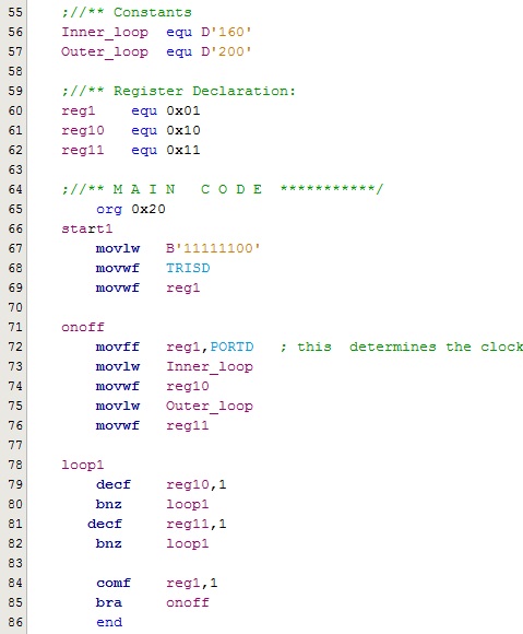
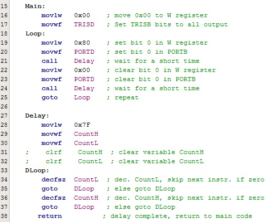
Code Example: Note that the second example is generating a DELAY using CALL function:
| Example 1 |
Example 2 |
 |
 |
![]()
![]()
![]()
![]()

